Field Oriented Control
Field Oriented Control (FOC) consists on controlling the stator currents represented by a vector in a 2-D time-invariant space \(dq\). The \(dq\) space is an orthogonal space aligned with the rotor: flux is aligned with \(d\) and torque is aligned with \(q\). A set of projections is used to transform from a three-phase speed and time dependent system to \(dq\). As the transformations are just projections the controlled magnitudes are instantaneous quantities, making the control structure valid for transient and steady state.
It can be shown that in the \(dq\) space we have:
that is, by maintaining the rotor flux constant \(\psi_R\) we have that the generated torque \(T\) is directly proportional to the \(i_q\) stator current. We can then perform torque control by changing the \(i_q\) current reference. Because the speed and time dependency is removed from the \(dq\) space, the control strategy is also simplified as constant references are being controlled.
Space Vector
We have that for three-phase AC motors, voltages, currents and fluxes can be analyzed in terms of complex space vectors. First we define the \(abc\) space, given by the following three unit vectors in the complex space:
Then, the space vector for currents (same applies to other magnitudes) is defined as:
The definition above may sound abstract, but with some more context it can be better understood. Let us start by looking at the currents shape. Given a three-phase balanced AC system, we have that phase currents are sinusoidal in steady state, i.e.:
where \(I\) is the current magnitude, \(\omega\) is the rotation speed in rad/s and \(\phi_0\) is an arbitrary initial phase. \(\omega t\) is the instantaneous position, \(\theta\). Note that both rotation speed and instantaneous position are always in electrical terms. We can read from the equations that \(i_b\) lags \(i_a\) by \(\frac{2 \pi}{3}\) rad, and \(i_c\) lags \(i_b\) by the same amount. We can also observe that the following equality holds as the system is balanced:
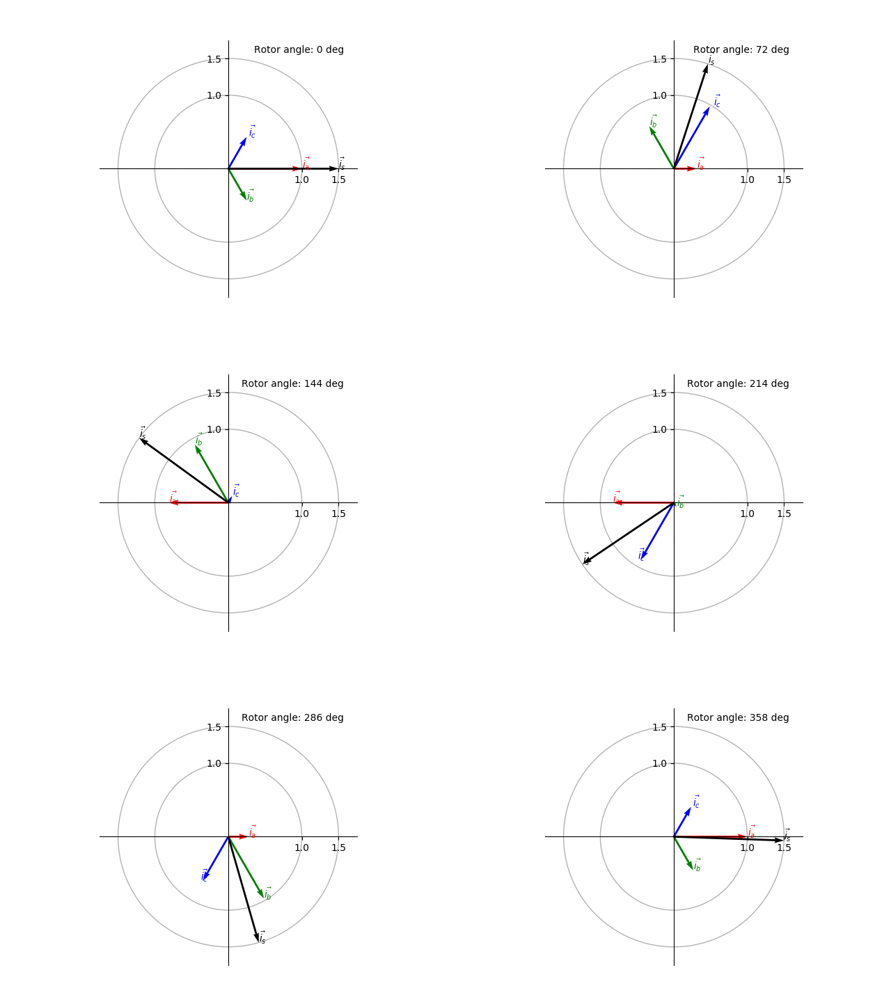
Using the above equations we can plot the space vector and its components as a function of the rotor position (Fig. 5). The space vector can be seen as a CCW rotating vector with rotation speed \(\omega\) in the complex space.

Fig. 5 Animated visualization of the space vector.
Clarke transform
Any non-orthogonal space indicates a redundancy in its axes. This is the case of the \(abc\) space, which can be reduced to the complex space. The complex space is usually referred in the motor control literature as the \(\alpha \beta\) space. In order to derive the transform from the \(abc\) space to the \(\alpha \beta\) space, we can take the projection of the space vector components into the \(\alpha \beta\) axes, that is:
Using the equality \(i_a + i_b + i_c = 0\), we can further simplify the expressions:
This transform is known as the Clarke transform, which in matrix form is:
It is important to note that \(\det{\mathbf{C}} \neq 1\), so the transform is not power-invariant. Its inverse is defined as:
Park transform
After the application of the Clarke transformation, we still have quantities that are speed and time dependent. Assuming we have knowledge of the rotor position, \(\theta = \omega t\), we can de-rotate the \(\alpha\beta\) space, therefore removing the speed and time dependency. The new frame will actually be a rotating frame and it is known as the \(dq\) space, the space mentioned at the beginning.
In order to derive the transformation we need to again project the \(\alpha\beta\) components to the rotating frame. The transform is known as the Park transform and it is actually the well-known 2-D rotation matrix in its inverse form as we are de-rotating or moving clock-wise.
In its inverse form it is given by: