Current sampling
Knowledge of phase currents is at the core of Field Oriented Control as they are the controlled variables. Multiple methods can be used in order to measure motor phase currents, being one of the most populars the usage of shunt resistors. We will also see that current sampling is tightly related to the PWM control signals and hence the modulation scheme.
Shunt resistors
It can be demonstrated that current flows through the shunt resistor when the low transistor is turned on. Therefore, current measurements need to be synchronized with the PWM switching times.
Only two phase currents are required to know the third one, as in a balanced system all currents sum zero. If we measure \(i_a\) and \(i_b\), \(i_c\) is also known. However, it is not always possible to sample the same currents as we are limited by the time the low side is active. The detailed analysis will be limited to the first sector case, for other sectors the same procedure can be followed.
SV-PWM
When using the SV-PWM modulation technique we have that the duty cycles take a particular shape that will condition the sampling of the currents. If we look at the first sector we have that duty cycles look like the animation shown in Fig. 1 (dead-time ignored for simplicity).
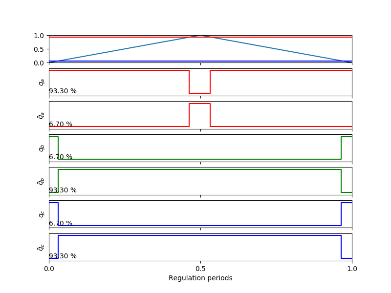
Fig. 1 Duty cycles for the first sector when using SV-PWM.
Actually, other sectors are just a combination of what we have in Fig. 1, only having direction changes in the linearly varying phase.
(Source code, png, hires.png, pdf)

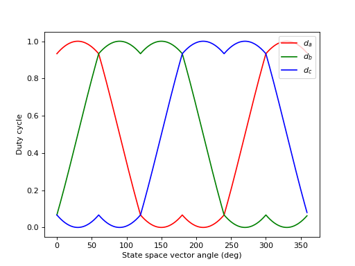
Fig. 2 SV-PWM duty cycles shape.
Summarizing, we will always have the following situation:
A phase with a high duty cycle, with its maximum at half of the period.
A phase that varies linearly either increasing or decreasing over a wide range of duty cycles.
A phase with a low duty cycle, with its minimum at half of the period.
We will use this information in the next section when designing the sampling strategy.
Sampling strategy
Because phase currents flow through the shunt resistor when the low-side is ON it is clear that we need to synchronize the measurements with the PWM signals. As we are on a balanced system, we can just measure two phase currents instead of all three. We also need to consider the modulation scheme (SV-PWM) in order to understand the limitations we have. As usual we will focus on analyzing the first SV-PWM sector and extrapolate the results to other sectors. Fig. 4 provides a timing diagram for the first sector which will be useful for the analysis.

Fig. 4 Duty cycles and current shapes for sector 1
Variable |
Description |
|---|---|
\(\mathrm{T_{RISE}}\) |
Time taken by the current signal to rise and stabilize to its nominal value after a bottom transistor switch-on event. |
\(\mathrm{T_{NOISE}}\) |
Time during which electric noise is present on a phase due to another phase bottom transistor switch-on event. |
\(\mathrm{T_{SAMPLE}}\) |
Time taken to sample the currents. |
\(\mathrm{DT}\) |
Dead-Time is a small time added to the PWM signals so that upper and bottom transistors do not change state at the same time thus avoiding shoot-throughs. |
In order to derive a simple sampling strategy we will assume that sampling is always started at the middle of the PWM period. When sampling currents we always need to skip the measurement of the phase that can be potentially OFF in the active sector. In case of sector one, this happens for phase a, meaning we will need to sample phases b and c. Fig. 1 provides animated duty cycle waveforms that can help on understanding the given concepts. The same reasoning can be performed for the other sectors, leading to the results shown in Table 1.
Sector |
Phases to be sampled |
|---|---|
1 |
b, c |
2 |
a, c |
3 |
a, c |
4 |
a, b |
5 |
a, b |
6 |
b, c |
The only condition we must fulfill is that the time the low side is ON is big enough to allow sampling the currents. The lowest time the low side is ON is given by:
If we take SV-PWM equations we have that the maximum PWM duty cycle for the phases to be sampled is:
As we sample at the middle of the period, we need then:
which results in:
If this condition is not met, PWM frequency should be reduced.